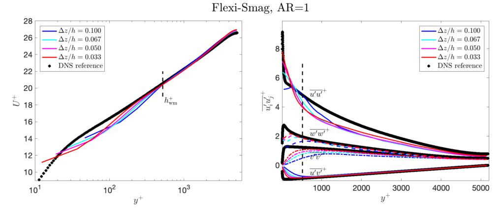
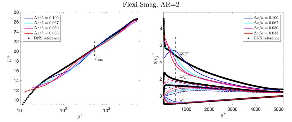
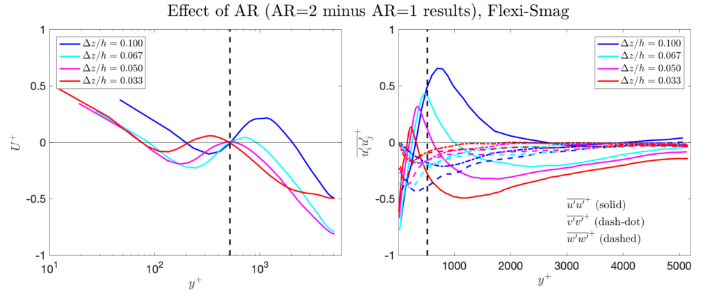
The Flexi code (Hindenlang et al, 2012 is a Discontinuous Galerkin Spectral Element (DGSEM) code developed in the Numerics Research Group at the University of Stuttgart. The code is open source and can be downloaded from http://www.flexi-project.org/.
The under-resolved simulations are stabilized by a skew-symmetric splitting of the advective terms of the Navier-Stokes equations (Flad and Gassner, 2017). Specifically, the flux formulation of Pirozolli (Pirozolli, 2010) is employed, leading to a dissipation-free and kinetic-energy preserving semi-discrete system. For the numerical fluxes at the cell interfaces, a low-dissipation variant of the Roe Riemann solver (Oßwald et al, 2015) is used. In the results shown here, the sub-grid scales are modeled using the classical Smagorinsky model with a model constant of 0.11.
The coupling procedure between LES and wall-model generally follows the method described here. The wall-model in Flexi is the algebraic Spalding formula which is solved iteratively using Newton’s method. Only very few iterations are necessary, since good starting values are known from explicit formulae in the different regions of the boundary layer, making the cost of computing the fluxes for the wall-model nearly negligible. This is especially true since the wall-model is evaluated only once every time step, and not for each stage of the Runge-Kutta time integration scheme. The walls are treated as adiabatic, so no additional solver step for the wall heat flux has to be employed.
The instantaneous LES solution at the interface location is computed using an interpolation from the polynomial representation of the DG solution at this specific position. In a pre-processing step, the interface location can be defined freely (at 10% of the channel half-height \(h\) in this case) and the information needed for the interpolation is stored. This includes the coordinates of the interface in reference space, an identifier for the cell containing the interface and the vectors needed to rotate the velocity in a wall-parallel coordinate system. For parallel computations, the solution at the interface is communicated to the cells at the wall (where the wall-model is evaluated) using the message passing interface (MPI), if needed. Since only surface-based data must be exchanged, the cost of this communication is again nearly negligible.
Since the boundary conditions for the DG method are enforced in a weak sense, the fluxes for the momentum in wall-tangential direction can be directly replaced by the fluxes calculated from the wall-model. The flux for the wall-normal direction is computed as in the non-modeled case.
All results shown were generated using an 8th-order approximation. Since the discretization of the computational domain is thus based on cells that contain 8 degrees of freedom per direction each, the used meshes had to be slightly adapted. The following table contains the \(y\)-coordinates of the cell interfaces for the different meshes, for the lower half of the channel only:


